Engine 1 x dimmer + 2 x switches
Description
This package implements the engine of the solar router which determines when and how much energy has to be diverted to three loads using three channels, or a single load with three channels like a water heater with three heating resistors.
The engine uses two relays to control different loads, with an additional regulator for fine-grained power control. The loads are activated sequentially as more power becomes available:
- First channel: Relay 1 (On/Off control)
- Second channel: Relay 2 (On/Off control)
- Third channel: Dimmer regulator (Variable power control)
When power needs increase:
- First, the regulator on channel 3 gradually increases power
- When regulator reaches 33.33%, relay 1 activates
- When regulator reaches 66.66%, relay 2 activates
Engine 1 x dimmer + 2 x switches calls the power meter every second to get the actual energy exchanged with the grid. If energy produced is greater than energy consumed and exceeds the defined exchange target, the engine determines the appropriate combination of relays and regulator opening to reach the target.
Engine automatic regulation can be activated or deactivated with the activation switch.
How to wire the relay (Channel 1 & 2)
- Line on the Relay Common (COM)
- Normally Open (NO) of the Relay from the input Load directly to the Load
How to wire the dimmer regulator (Channel 3)
- Just like any other dimmer from the input Load directly to the Load, and without any connection to other relay or channel 1 & 2.
Wiring schema example

Configuration
To use this package, add the following lines to your configuration file:
green_led_pin and yellow_led_pin in the vars section as shown in the example above. Variables
| Variable | Required | Default | Description |
|---|---|---|---|
green_led_pin | yes | — | GPIO pin for the green status LED |
yellow_led_pin | yes | — | GPIO pin for the yellow network/error LED |
green_led_inverted | no | 'False' | Set to 'True' if the green LED is active low |
yellow_led_inverted | no | 'False' | Set to 'True' if the yellow LED is active low |
hide_regulators | no | 'True' | Set to 'False' to expose regulator sensors in Home Assistant |
hide_leds | no | 'True' | Set to 'False' to expose LED state sensors in Home Assistant |
Power Distribution
The engine divides the total available power into three equal portions (33.33% each). This allows for smooth transitions between different power levels and efficient distribution of excess solar power across multiple loads.
Bypass tempo adjustment
The Bypass Tempo determines how many consecutive regulations at 33.33% or 66.66% are needed before activating the bypass relay. A lower value will make the bypass more reactive but might cause more frequent switching (flickering). Because there is roughly 1 regulation per second, Bypass Tempo can be approximated as the time in seconds with the regulator at 33.33% or 66.66% before the relays are activated.
Sensors
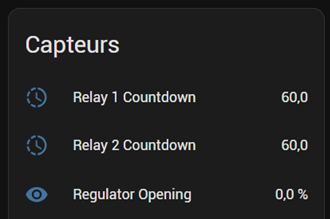
- Countdown for relay no. X For each relay, the current countdown is displayed. Initially the countdown is equal to the tempo bypass value, then with each energy regulation where the controller is at 100% the countdown is reduced, finally when the countdown is equal to zero the relay is activated.
- Regulator opening Hidden by default (see
hide_regulators), displays the regulator level (TRIAC or SSR).
This package requires the use of the Regulator Relay package AND a regulator package (TRIAC or SSR). Do not forget to also include them.
You can find below the example of configuration for relays:
Relay IDs
Relay unique IDs cannot be changed when using this engine.