Triac Regulator
Description
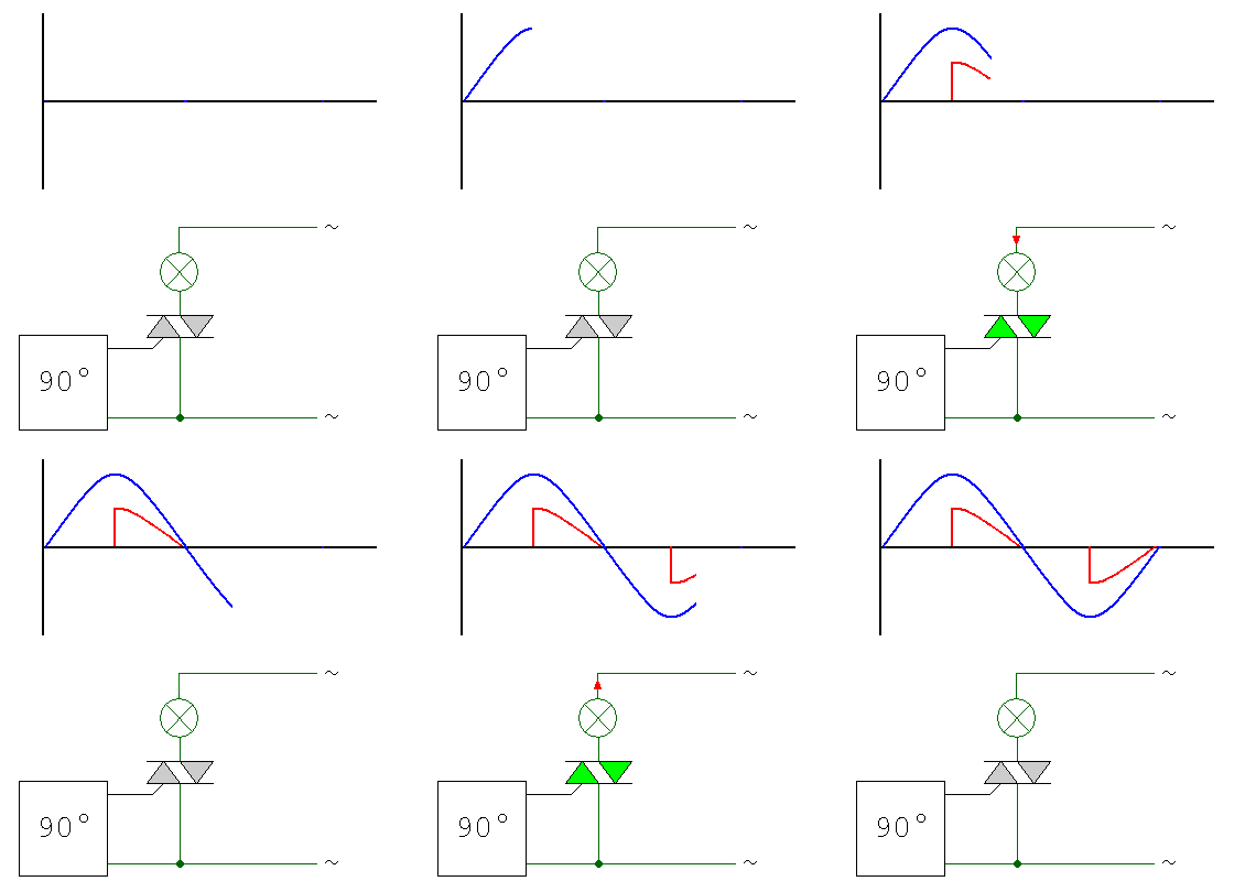
This regulator performs a Phase Control Regulation.
A triac is able to split the current sent to the load to reduce the power transmitted. This component is the base of AC Dimmers.
Diagram

How does this regulator work?
If you want to know more how a triac can regulate the transmited energy, you can refer to Wikipedia.
The following diagram shows how the input sinus is cut to reduce the energy transferred to the load:
Hardware
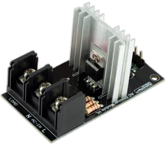
In this package, we propose to use a board manufactured by RobotDyn.
Warning
The triac is supposed to support up to 24A (which represents a power greater than 5500W). The heat sink is undersized regarding the level of energy which is supported by the triac. It is then recommended to replace the heat sink with a bigger one.
Wiring Diagram
The following schematic shows the wiring of the board: 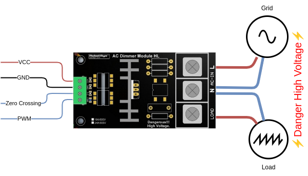
Configuration
To use this package, add the following lines to your configuration file:
Variables
| Variable | Required | Default | Description |
|---|---|---|---|
regulator_gate_pin | yes | — | GPIO pin for triac gate/PWM control. |
regulator_zero_crossing_pin | yes | — | GPIO pin for zero crossing detection. |
regulator_zero_cross_inverted | no | false | Set to true if zero crossing detection is done on high level (resolves flickering issues). |