Engine 1 x switch
Description
This package implements the engine of the solar router which determines whether energy can be diverted to a local load or not.
Engine 1 x switch reads the power meter on every update to get the actual power consumed. If the energy sent to the grid exceeds the start level (W) for the configured start tempo (s), the relay closes to consume the energy locally. When the energy sent to the grid drops to the stop level (W) for the stop tempo (s), the relay opens and local consumption is stopped.
Engine automatic regulation can be activated or deactivated with the activation switch.
The following schema represents the consumption with this engine activated:
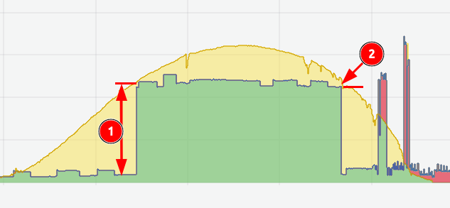
Legend:
- Green: Energy consumed coming from solar panels (self consumption)
- Yellow: Energy sent to the grid
- Red: Energy consumed coming from the grid
How does it work?
- ① The yellow part of the graph shows the start level. When the energy sent to the grid reaches the start level, energy is diverted locally.
- ② The yellow part of the graph shows the stop level. In this example 0 W.
Carefully set the start and stop levels
The start level has to be greater than the power of the load plugged to the solar router. If not, as soon as the energy is diverted to the load, the stop level will be reached and you will see the router switching between ON and OFF (based on the temporisation you defined).
Finely adjust start and stop tempo
The start and stop tempo determine the responsiveness of the regulation. These delays must be finely adjusted to avoid oscillations. For example, if you have an electric stove, pay attention to the heating delays.
Configuration
To use this package, add the following lines to your configuration file:
When this package is used it is required to define green_led_pin and yellow_led_pin in the vars section as shown in the example above.
Variables
| Variable | Required | Default | Description |
|---|---|---|---|
green_led_pin | yes | — | GPIO pin for the green status LED |
yellow_led_pin | yes | — | GPIO pin for the yellow network/error LED |
green_led_inverted | no | 'False' | Set to 'True' if the green LED is active low |
yellow_led_inverted | no | 'False' | Set to 'True' if the yellow LED is active low |
hide_regulators | no | 'True' | Set to 'False' to expose relay state sensors in Home Assistant |
hide_leds | no | 'True' | Set to 'False' to expose LED state sensors in Home Assistant |